
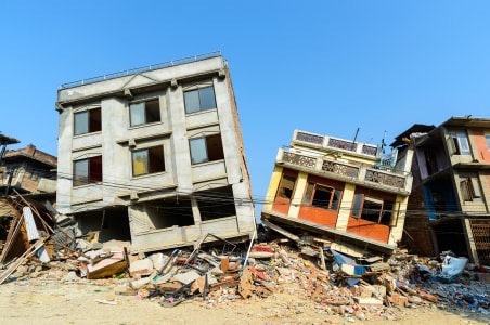
Minimize damage and maximize safety
1. EARTHQUAKES ARE NATURAL PHENOMENA
Seismic events are natural phenomena that may occur with lower or higher probability (risk) in specific geographical areas (Fig. 1.1). Seismic risk of a structure which refers to the potential damage or failure, involves two key factors:
- Seismic hazard depends on ground acceleration during seismic events and vulnerability of the structure depending on the type of structure and importance class.
- Earthquakes can lead to many structural and non-structural failures resulting in economic losses, injury or loss of life.
Although Australia isn’t the first place that comes to mind when it comes to impact of seismicity in construction when compared to countries like New Zealand, Japan and Indonesia, Australia experience earthquake almost daily, but of very low intensity, going mostly unnoticed. Approximately every 5 years, Australia experience an earthquake of magnitude 6 or more, which has the potential to cause significant damage and loss of life (Fig. 1.2).
Seismic design includes safety features, prevents collapse by withstanding the forces generated due to shaking of ground during earthquake. The target is not only to reduce damage but also to help ensure the functionality of any structure during seismic event. It’s important to note that many of the earthquakes of moderate to high magnitude can cause significant damage (Fig. 1.3), hence monitoring seismic activity is crucial for disaster mitigation.
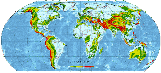
Fig. 1.1: Global seismic hazard map (Source: GSHAP)
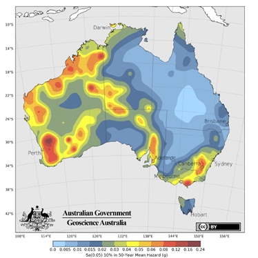
Fig. 1.2: Australian seismic hazard map (Source: NSHA18)
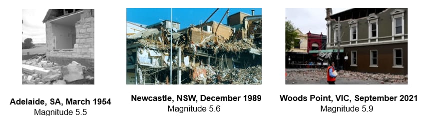
Fig. 1.3: Notable earthquakes in Australia
2. STRUCTURAL AND NON-STRUCTURAL APPLICATIONS REQUIRE SEISMIC DESIGN
Structural and non-structural connections both need to be designed to withstand seismic force. While structural applications obviously require seismic design for safety and sustainability of structures, damage of non-structural connections can also lead to significant damage, safety, economy and emergency services etc. (refer to Fig. 2.1)
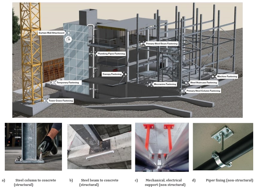
Fig. 2.1: Typical illustration of a building with different structural and non-structural applications
Extensive research shows that the costliest repairs in most commercial buildings caused by a seismic event are found in non-structural systems, such as mechanical or electrical supports or utilities fastening (Fig. 2.2). Many non-structural installations must be designed properly to meet safety requirements [1].
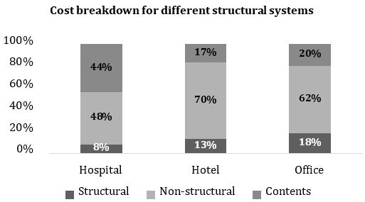
Fig. 2.2: Loss assessment of structural and non-structural components [1]
3. SEISMIC CATEGORIES AND QUALIFICATION FOR POST-INSTALLED ANCHORS
Seismic categories are used to assess the potential of seismic hazard for structures and define the design with the aim of making structures anti-seismic. According to AS 5216:2021 Appendix F, seismic performance of anchors is categorized in two types: C1 and C2. C1 represents a generally low level of hazard whereas C2 indicates a higher level of seismic risk.
- Performance category C1 provides anchor capacities only in terms of resistances at the ultimate limit state (maximum assumed crack width Δw = 0.5 mm).
- Performance category C2 provides anchor capacities in terms of both resistances at the ultimate limit state and displacements at the damage limitation state and ultimate limit state (maximum assumed crack width Δw = 0.8 mm).
In all cases, no anchors are allowed to be installed in areas of the concrete members where section plasticization is expected, i.e., in plastic hinges (see Fig. 3.1), because the crack width will likely exceed the limit of Δw = 0.8 mm), for which the anchors are assessed.
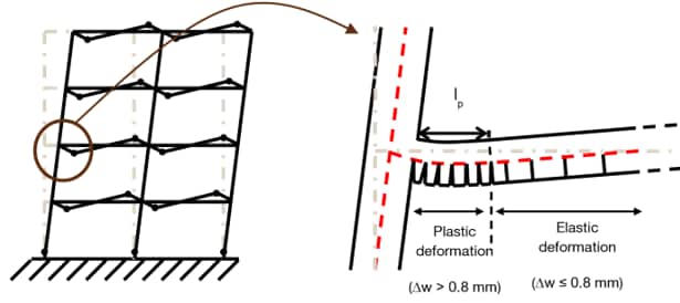
Fig. 3.1: Example of plastic and elastic portions of reinforced concrete members [2]
Table F.3.2 of AS 5216:2021 [3] includes the recommendation for the use of anchors assessed according to seismic category C1 and C2 as a function of the site sub-soil class and building importance level according to AS 1170.4:2024 [4].
Qualification against seismic performance is guided by EAD 330232 [5] for post-installed mechanical anchors and EAD 330499 [6] for post-installed bonded anchors with required performance tests as mentioned for seismic category C1 and C2. For performance category C1, tests are done for pulsating tension and alternating shear load and for performance category C2, tests are done up to failure for pulsating tension, alternating shear as well as tests under crack cycling. Continuous measurement is done for test forces and displacements at certain intervals. Both EADs are referred in AS 5216:2021 [3].
4. DESIGN OF POST-INSTALLED ANCHORS IN SEISMIC AS PER AS 5216
The design value of seismic actions is determined according to AS 1170.4 [4] and AS 5216 [3] Appendix F considering all possible effects for vertical and horizontal ground motions for both structural and non-structural connections.
The design requirement of post-installed anchors in both static and seismic conditions differ significantly as static condition involve relatively constant loads whereas seismic condition require the anchor to resist dynamic and sometimes unpredictable loads. The key differences are summarized in Table 4.1.
Table 4.1: Key differences between static and seismic
To protect the connections during earthquake, different design strategies are followed, a) Capacity design b) Elastic design and c) Ductile design 

Fig. 4.1: Seismic design by protection of fastening
Design resistance against seismic loading:
Additional factors of 𝛼𝑔𝑎𝑝 and 𝛼𝑒𝑞 (refer to AEFAC TN-10, section 10) are used on static resistance against different failure modes.
The characteristic seismic resistance 𝑅𝑘,𝑒𝑞 = 𝛼𝑔𝑎𝑝 ∙ 𝛼𝑒𝑞 ∙ 𝑅𝑘0,𝑒𝑞
➢ 𝛼𝑔𝑎𝑝 is the reduction factor given in the ETA to consider the inertia effect due to the annular gap between anchor and fixture (i.e., hammering effect) under shear loading which is 0.5. Using Hilti filling set (Fig. 4.2) and by filling the clearance of the hole, 𝛼𝑔𝑎𝑝 can be 1.0.
➢ 𝛼𝑒𝑞 is the factor to consider the influence of seismic actions and associated cracking depending on:
a) Formation of large crack widths; and
b)Uneven tension stiffness of fasteners in a group due to random crack distribution The value of 𝛼𝑒𝑞 for different types of anchors can be taken from AEFAC TN-10, Table 6.

Fig. 4.2: Hilti filling set
The power factor is used in seismic loading as 𝑘15 = 1 for steel failure, 0.67 for fastenings with a supplementary reinforcement and 1 in all other cases.
Displacements in Damage limit state and Ultimate limit state are defined for all anchors qualified for seismic category C2 in their respective ETA approval. To consider the limitation in maximum displacement, loads are reduced using the ratio of actual and limiting displacement.
Post-installed anchors should have the necessary ETA (European Technical Assessment) to be selected and used in seismic condition and the characteristic resistance and displacement values need to be taken from that document.
5. HOW TO DO SEISMIC DESIGN USING PROFIS ENGINEERING?
The user-friendly, cloud-based structural engineering design software PROFIS Engineering by Hilti offers design options for seismic loading according to AS 5216. In the design interface under the “Load/ calculation type” tab, load type needs to be selected for seismic, further seismic category and design type as shown in Fig. 5.1. The “Seismic displacement” can also be selected from available options.
Also, in the “Anchor” tab, the option for “Fill holes” require to be checked as design resistance in seismic varies for anchor with or without hole clearance. After selecting the load types as “Seismic”, the recommended / approved options for post-installed anchors will appear in the list for the defined application. In the design report generated from the analysis, the seismic condition details are also mentioned.

Fig. 5.1: Seismic design inputs for anchors in PROFIS Engineering
6. CONCLUSION
The seismic design of post-installed connections is important to ensure anchors’ performance against cyclic loading and help to minimize risk and maintain safety. The design specific to account seismic condition needs to be performed as the properties of anchors get changed during seismic event with respect to dynamic repeated loading, ductility etc. In absence of proper seismic design, for structures situated in seismic prone area, the anchors may fail at an unpredictable load level leading to significant damage, loss of critical infrastructure or even risk of life.
To start designing, visit PROFIS Engineering Suite structural design software - Fastening design software - Hilti Australia
You can reach out to us for technical support, here: Technical Advice Services - Hilti Australia
REFERENCES
[1] S. Taghavi and E. Miranda, "Seismic Performance and Loss Assessment of Nonstructural Building Components," in National Conference on Earthquake Engineering, Boston, 2002.
[2] M. S. Hoehler, Behavior and Testing of Fastenings to Concrete for use in Seismic Applications, PhD Thesis, California, August 2006.
[3] AS 5216:2021: Design of post-installed anchors and cast-in fastenings in concrete.
[4] AS 1170.4:2024: Structural design actions, Part 4: Earthquake actions in Australia.
[5] AEFAC - TN10: Prequalification & design requirements for fastenings under seismic actions.
[6] EOTA EAD 330232-01-0601: Mechanical fasteners for use in concrete, Brussels: EOTA, 2021.
[7] EOTA EAD 330499-02-0601: Bonded fasteners and bonded expansion fasteners for use in concrete, Brussels: EOTA, 2022.
The information provided in this article is for general information purposes only. While we strive to ensure the accuracy and reliability of the information presented, it is not intended as legal, technical or professional advice.
Hilti makes no representations or warranties of any kind, express or implied, about the completeness, accuracy, reliability, or suitability, with respect to the article for any purpose.
